
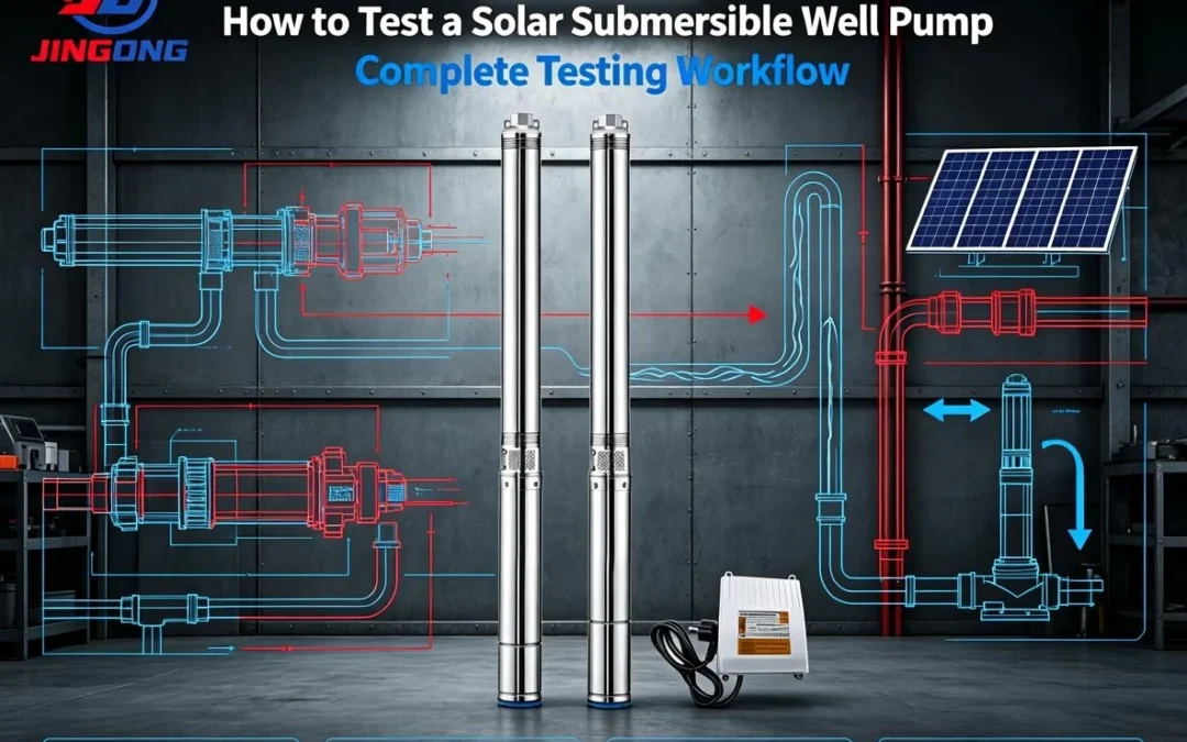
Most online tutorials treat a Solar Submersible Well Pump like a standard AC unit—and that oversight leads to misdiagnosis, unnecessary returns, and costly downtime. At Jingong Tech, we’ve spent 15 years manufacturing and troubleshooting solar submersible well pumps, surface pumps, booster pumps, and diesel engine pumps for global markets. This guide is built on real-world field data, not just theory.
Unlike AC pumps, DC solar pumps involve variable PV input, MPPT controllers, and BLDC motor windings that require specific multimeter settings. In this article, we’ll walk through a 6-step diagnostic process that aligns with IEC 60034 and GB/T 2818-2014 standards. Whether you are a distributor, an irrigation contractor, or a DIY off-grid homeowner, this guide will help you determine if the issue lies with the PV array, the controller, or the pump itself.
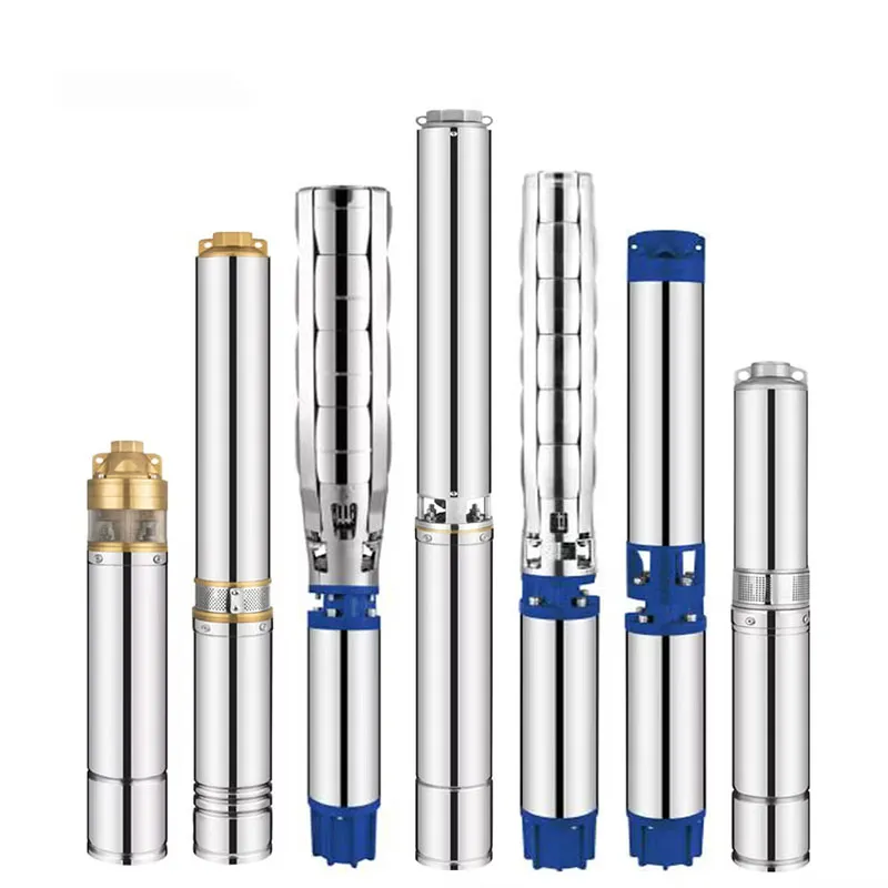
Pre-read: If you are currently sourcing a replacement, explore our high-efficiency Solar Submersible Well Pump collection ranging from 0.5 HP to 10 HP.
1: Pre-Test Preparation — Tools, Safety, and PV-Specific Checks
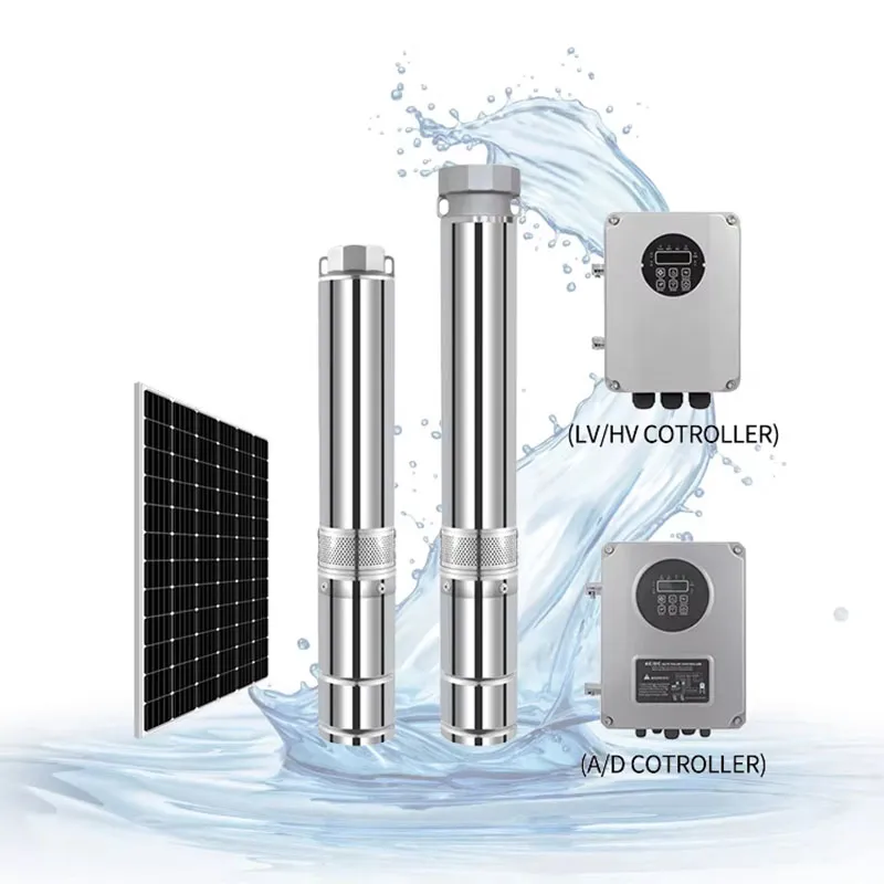
1.1 Essential Tools for Solar Pump Diagnostics
Do not rely on a $10 hardware store multimeter for a $1,000 pump system. Precision matters.
- True-RMS Digital Multimeter (CAT III 600V): Essential for accurate DC voltage readings. Cheap meters often fail to capture the true open-circuit voltage (Voc) of a PV array.
- Megohmmeter (500V DC Insulation Tester): A standard multimeter cannot accurately perform insulation resistance tests. A megger is required to detect moisture ingress.
- DC-Capable Clamp Meter: Most clamps only read AC. Ensure yours specifies DC current measurement.
- Lockout/Tagout Kit: Safety compliance prevents arc-flash incidents during PV disconnection.
1.2 Safety First: Disconnecting the PV Array
A solar submersible well pump is powered by DC electricity, which arcs differently and is harder to break than AC. Follow this sequence strictly:
- Cover the solar panels with an opaque tarpaulin or disconnect them at the combiner box.
- Wait 5 minutes for the MPPT controller capacitors to discharge fully.
- Use your multimeter to verify 0V at the PV input terminals before touching the pump output terminals.
1.3 Visual Pre-Inspection
Before turning the multimeter on, inspect the wellhead splice box. According to our service logs, 40% of “failed” solar submersible well pumps actually suffer from water-logged connectors at the wellhead. Check for corrosion, cracked conduit, and ensure the voltage rating on the pump nameplate matches the PV array configuration.
2: Electrical Principles of a Solar Submersible Well Pump
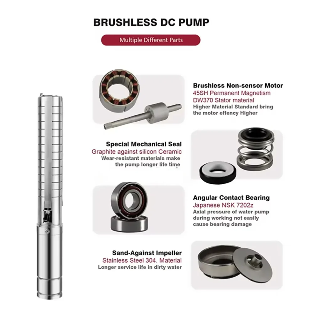
To test effectively, you must understand the architecture. A conventional AC pump connects directly to the grid. A Solar Submersible Well Pump manufacturer operates on a different logic:
- Power Source: PV Array (Variable DC).
- Intermediary: MPPT Controller (Converts DC voltage to optimal frequency/power).
- Motor: Typically Brushless DC (BLDC) with a 3-phase star winding configuration.
Because the motor relies on permanent magnets, the winding resistance is often higher than an induction motor of similar size. For instance, a 1 HP DC solar pump might read 3–8 Ohms per phase, whereas an AC equivalent might be under 1 Ohm. This distinction is critical for accurate diagnosis.
3: Step-by-Step Multimeter Testing Process

This is the core of the diagnostic procedure. Ensure the pump is disconnected from the controller output during resistance tests.
3.1 Multimeter Calibration and Range Selection
Set your multimeter to the correct ranges before testing:
- DC Voltage (V—): Use the 600V or 1000V range for PV array checks.
- Resistance (Ω): Use the 200Ω range for most solar submersible well pump windings.
- Continuity: Use the buzzer setting for cable checks.
Pro Tip: Short your probes together to establish a zero baseline. This accounts for lead resistance.
3.2 Test A: PV Array and Controller Input Voltage
With the PV array uncovered (and extreme caution), measure the voltage at the controller’s PV input terminals.
- Voc (Open Circuit Voltage): Should match the panel specs within 10%.
- Vmp (Voltage at Maximum Power): Measured under load. If Vmp exceeds the controller’s max input rating, the controller will fail.
3.3 Test B: Pump Cable Continuity
Check the submersible cable for breaks between the controller and the wellhead.
- Normal: Less than 2Ω resistance.
- Fault: OL (Open Loop) indicates a severed conductor or a corroded splice.
3.4 Test C: Motor Winding Resistance (Critical Step)
Disconnect the 3 phase wires (U, V, W) from the controller. Measure the resistance between each pair (U-V, V-W, W-U).
| Reading | Diagnosis |
|---|---|
| Balanced (±5%) | Healthy Winding |
| OL / Infinite | Open Circuit (Burnt winding) |
| 0 – 0.5Ω | Short Circuit (Turn-to-turn fault) |
| >10% Deviation | Partial Short (Pump will overheat) |
For a standard solar submersible well pump, these values confirm the integrity of the motor core.
3.5 Test D: Insulation Resistance (Megger Test)
Using a 500V Megger, connect one lead to the joined phase wires and the other to the pump housing.
- Cold Reading: ≥ 50 MΩ (New/Healthy).
- Hot Reading: ≥ 2 MΩ (Minimum acceptable).
- Fault: ≤ 0.5 MΩ indicates water has breached the seals.
Low insulation is the leading cause of solar submersible well pump failure in agricultural settings.
3.6 Test E: Load Current Test
With the system running on a sunny day, use a DC clamp meter on one phase wire.
- Normal: 90% – 110% of the rated amps on the nameplate.
- High Current: Indicates sand locking, a blocked impeller, or winding shorts.
- Low/Zero Current: Suggests a dry well, controller shutdown, or broken connection.
4: Fault Diagnosis Chart (Quick Reference)

Print this chart for your field technicians. It synthesizes Jingong’s engineering database for rapid troubleshooting.
| Symptom | Likely Cause | Action |
|---|---|---|
| Pump Not Running | Low Sun / UVLO / Open Winding | Check PV Voc; Test winding continuity |
| Low Water Flow | Well Level Drop / Clogged Strainer | Sound well depth; Clean inlet |
| Intermittent Operation | MPPT Hunting / Cloudy Weather | Add panels in parallel; Check well drawdown |
| Burnt Smell / Tripping | Insulation Failure / Short Circuit | Perform Megger test; Replace motor |
5: Common Solar Submersible Well Pump Faults & Fixes
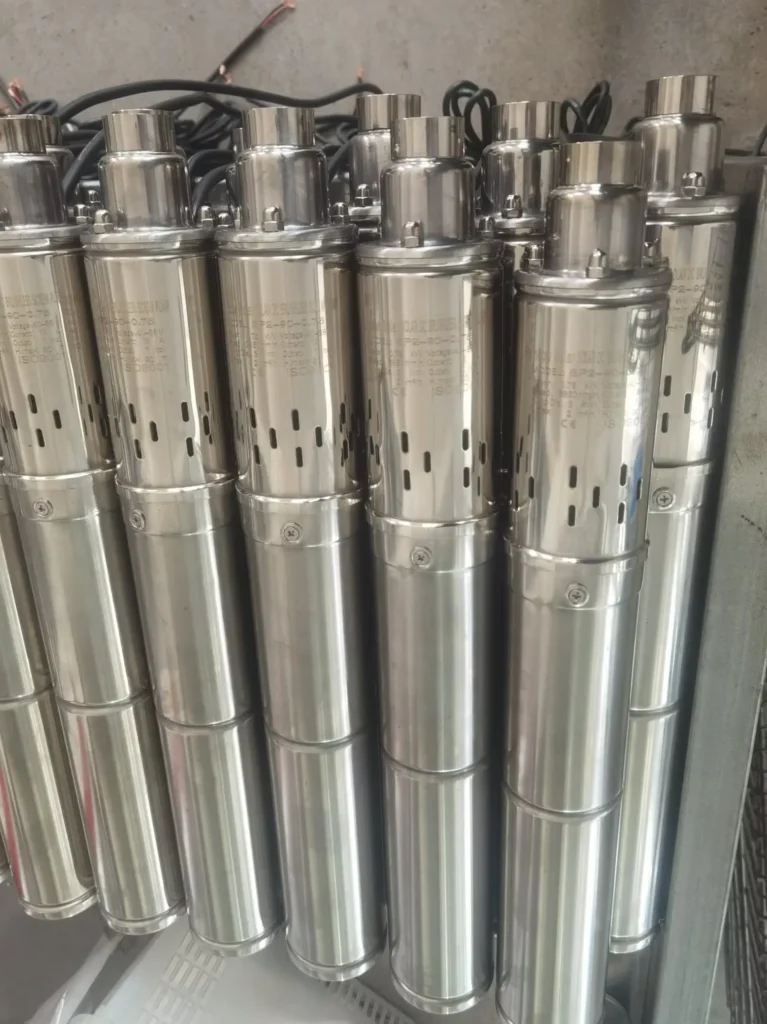
Based on Jingong’s global support experience, here are the top four failure modes:
- The “Dry Run” Scenario: Often misdiagnosed as electrical failure. If the well water level drops below the pump intake, the motor spins but delivers no water. Install a float switch or level sensor.
- Sand Lock: Common in new boreholes. Sand enters the impeller, seizing the rotor. Requires pulling the pump and flushing the well.
- Controller Overload: If the solar submersible well pump draws too much current (e.g., due to head height changes), the controller cuts power. Verify Total Dynamic Head (TDH).
- Seal Failure: The mechanical seal is the weakest link. Once it fails, water enters the motor, destroying the windings. Regular maintenance checks are vital.
6: Cross-Pump Type Comparative Testing Tips
Jingong manufactures a wide range of fluid transfer equipment. Understanding the differences in testing procedures enhances your technical expertise:
- Solar Submersible Well Pump (DC): Focus on PV input and DC resistance.
- Conventional AC Submersible: Focus on start/run capacitors and AC inductance.
- Surface Booster Pumps: Focus on priming and pressure switch calibration.
- Diesel/Gasoline Pumps: Electrical tests are minimal (ignition/spark). Focus on mechanical compression and fuel delivery.
By mastering the nuances of the solar submersible well pump, you can confidently service any pump in your inventory.
Surface Pumps |
Diesel Pumps |
AC DC Deep Well Pumps
7: Frequently Asked Questions (FAQs)
Can you test a solar submersible well pump with a regular multimeter?
Yes, for basic checks like PV voltage and winding continuity. However, a regular multimeter cannot perform a proper insulation resistance test (requiring 500V DC) or measure DC load current without a DC-capable clamp attachment. For a definitive diagnosis of a solar submersible well pump, specialized tools are recommended.
Why is my solar well pump not pumping water?
Beyond electrical faults, the most common reasons are a dry well (water level below intake) or a clogged foot valve/strainer. Always check the physical well conditions before assuming motor failure.
What is the normal resistance for a solar pump motor?
It varies by horsepower. A 1 HP DC motor typically reads 3–8 Ohms per phase. A 5 HP motor reads 0.8–2 Ohms. The key is balance: all three phases (U, V, W) must be within 5% of each other.
How to tell if a solar pump motor is burned out?
Three indicators: (1) An open circuit (OL) or zero resistance on a winding test, (2) Insulation resistance below 0.5 MΩ, and (3) Scorched enamel smell from the motor. If you observe these, the solar submersible well pump motor requires rewinding or replacement.
Is DC solar pump testing different from AC pump testing?
Yes. AC pumps often include capacitors and operate on inductive reactance principles, while DC solar pumps rely on BLDC motor technology and require PV array analysis. The testing tools and safety protocols (DC arc-flash vs AC shock) differ significantly.
Part 8: Conclusion & Jingong Product Recommendation
Diagnosing a solar submersible well pump requires a systematic approach: PV Array → Controller → Cable → Windings → Insulation → Load. By following this guide, you minimize guesswork and protect your investment. At Jingong Tech, we engineer our pumps for durability, but proper testing ensures longevity.
If your diagnostics indicate a failing motor, consider upgrading to our latest generation of high-efficiency models:
- For Farms & Livestock: Our 72V/120V DC Helical Rotor Solar Submersible Well Pump. Ideal for high-head, low-flow applications.
- For Village Water Supply: Our 240V/300V DC Stainless Steel series. Built for corrosive water and high-volume output.
- For Hybrid Systems: Pair a solar submersible well pump with our Diesel Engine Backup Pumps for 24/7 reliability.
Need expert help? Send your multimeter readings to our engineering team. We provide free technical support to verified distributors and customers.
Request a Quote or Technical Support |View Installation Case Studies