
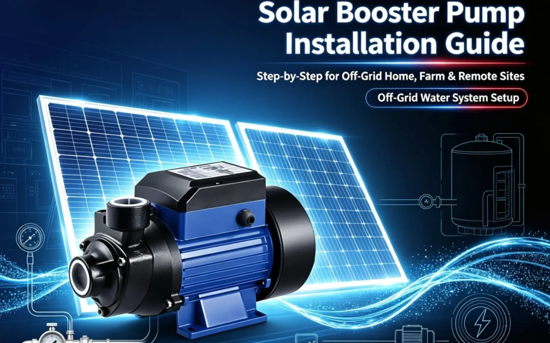
If you are planning a Solar Booster Pump Installation for residential water supply, farm irrigaton, or a remote off‑grid site, this guide walks you through the entire workflow—from site evaluation to final commissioning. As a pump manufacturer running export + field service for over 15 years, we built this tutorial around two product families we see most often on real projects: solar surface booster pumps and solar submersible pumps. We’ll also compare solar vs. diesel/gasoline pumps for hybrid setups where cloudy seasons matter.
A proper Solar Booster Pump Installation is not just “plug panels into pump.” Wrong wire gauge, shaded panels, or missing check valves are the top three reasons systems fail within 6 months. This guide prevents those mistakes.
1: What Is a Solar Booster Pump & Where It Fits (Application Scenarios)
1.1 Definition & Working Principle (Plain English)
A solar booster pump is a water pump driven by photovoltaic (PV) power—either direct‑DC (PV → MPPT controller → DC pump) or AC‑hybrid (PV → inverter → AC pump, often with battery or grid backup). “Booster” means the pump’s job is to raise pressure: either lifting water from a source (well / tank / river) or pressurising it for showers, drip irrigation, or high‑head delivery.
In a typical off‑grid solar water pump setup, the chain looks like this:
- PV Array → captures sunlight → DC electricity
- Charge Controller / MPPT → tracks maximum power point, regulates voltage
- Battery Bank (optional) → stores energy for dawn/dusk/night pumping
- Pump Unit → surface or submersible, driven by DC or inverted AC
- Pressure System → pressure tank + pressure switch + check valve
1.2 Core Advantages (Why Solar Over Diesel?)
| Factor | Solar Booster Pump | Diesel/Gasoline Pump |
|---|---|---|
| Fuel cost | $0 (sun is free) | Ongoing fuel + transport |
| Maintenance | Low (no engine, no oil) | High (filters, spark plugs, fuel lines) |
| Noise | Near silent | Loud, not yard‑friendly |
| Remote suitability | Excellent (no fuel logistics) | Needs fuel truck access |
| Weak point | Night / cloudy days (needs battery/hybrid) | Runs 24/7, fuel permitting |
We cover hybrid solar+diesel setups in our diesel pump section for farms with long rainy seasons.
1.3 Applicable Scenarios
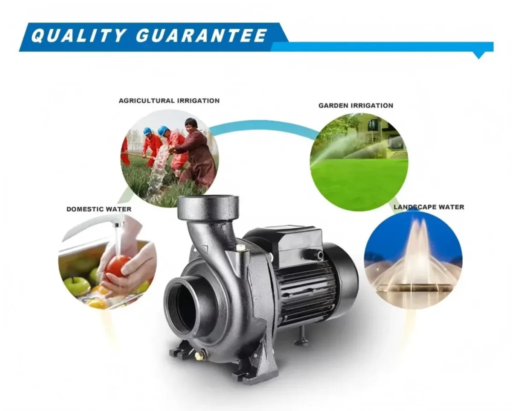
- Residential water supply – rural homes, cabins, villas without grid
- Farm irrigation – drip, sprinkler, orchard rows; pairs with solar timer
- Garden & livestock – animal drinking troughs, greenhouse misting
- Off‑grid community water – village well → rooftop tank systems
- Construction / temporary site – no grid yet, portable surface unit
1.4 Surface vs. Submersible: Which One Your Solar Booster Pump Installation Needs
This is the single biggest pre‑purchase decision. A wrong choice here = Solar Booster Pump Installation redo 3 weeks later.
| Solar Surface Booster Pump | Solar Submersible Booster Pump | |
|---|---|---|
| Mounting | Above ground, near water source or in pump house | Submerged in well / tank / river sump |
| Suction limit | ~8 m (self‑priming models up to 9 m) | No suction limit—pushes from below |
| Best for | Shallow wells (<8 m), tank boosting, river/lake shore | Deep wells (>8 m), borehole, cistern, riverbed |
| Installation difficulty | Easier – accessible for DIY | Harder – needs rope, check valve, anti‑sway |
| Maintenance | Easy – pump visible | Must pull out of well for service |
Both types are covered in detail in our surface pump range and submersible pump range.
2: Pre‑Installation Preparation & Site Evaluation
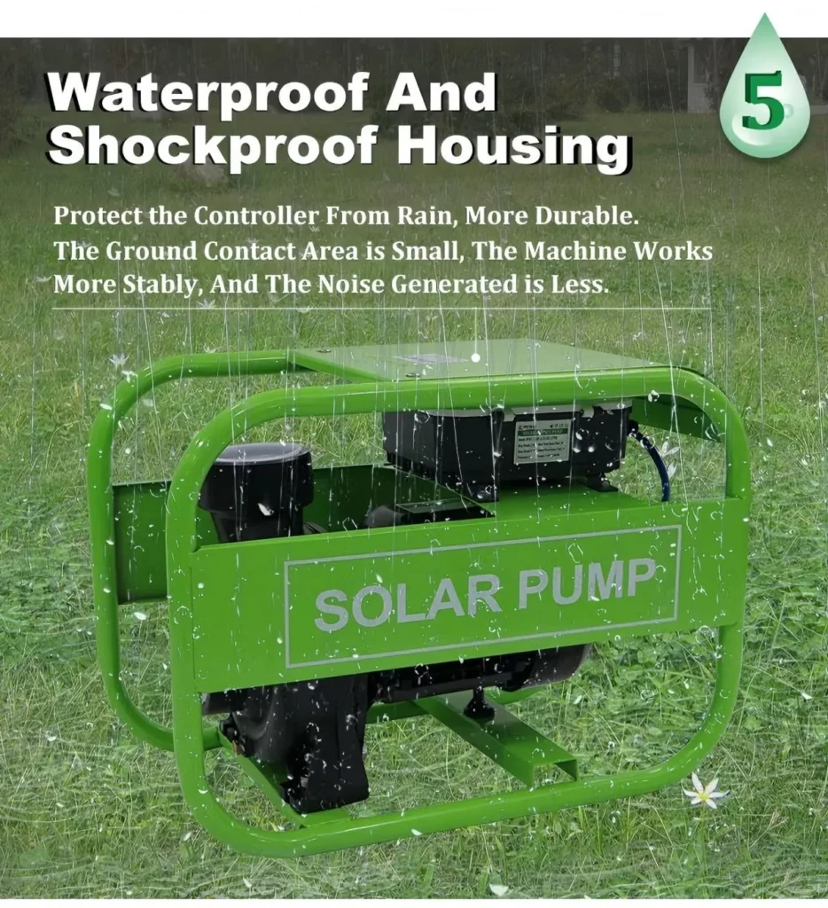
This module is where real engineers separate from generic blog posts. A careful pre‑check before your Solar Booster Pump Installation starts will save you 80 % of post‑launch service calls.
2.1 Safety First (Non‑Negotiable)
- Lock‑out / tag‑out any existing AC supply before touching wiring
- Use insulated hand tools (1000 V rated)
- Wear gloves + safety glasses; PV panels can still output 30–40 V open circuit even in shade—treat as live
- If pump is sub‑type, never pull by cable—use rope/strap on pump body
- Check dry‑run protection is enabled on controller before first power‑up
2.2 Site Evaluation Checklist
- Sun path – panels need south‑facing (N. hemisphere) or north‑facing (S. hemisphere), tilt ≈ local latitude ±5°
- Shadow audit – walk site at 9 AM / 12 PM / 4 PM. Chimneys, trees, water tanks cast longer shadows than you think. Even 10 % panel shading can cut output 50 % on series strings.
- Mounting surface – pump pad 30 cm above ground to avoid puddles / termite / flood. Concrete plinth preferred.
- Wind load – if you are in cyclone / monsoon zone, panel frames need diagonal bracing.
- Water source depth & quality – turbidity >0.1 % (sand/silt) means you need a foot valve + sediment filter before pump inlet.
2.3 System Matching Confirmation (Get the Numbers Right)
Mismatched PV → pump is the #1 cause of “solar pump not working” tickets. Before your Solar Booster Pump Installation, verify:
- Pump rated power (W) – label on motor nameplate
- PV array Voc / Vmp – must match controller input range. Example: 24 V pump → 2×12 V panels in series (~36 Vmp) + MPPT
- Battery bank – if included, Ah rating must cover at least 1.5× pump surge (motors draw 3–6× rated at startup)
- Wire run distance – long runs (>20 m) need thicker gauge to keep voltage drop <3 %
2.4 Tools & Accessories List (Print This)
✅ Pipe wrench, adjustable spanner
✅ Crimp tool + MC4 connectors
✅ Wire stripper, multimeter
✅ PVC primer + cement (or SS clamp set)
✅ Check valve (spring‑loaded, arrow → flow direction)
✅ Pressure switch + gauge
✅ Expansion/pressure tank (pre‑charged 1.5–2.5 bar)
✅ Fuse (on PV+ line, sized 1.25× array Isc)
✅ Charge controller (MPPT preferred over PWM for pump loads)
✅ Vibration damping pad (surface units)
✅ Rope/ nylon strap (submersible lowering)
3: Solar Booster Pump Installation Complete System Composition (Know What You Are Installing)
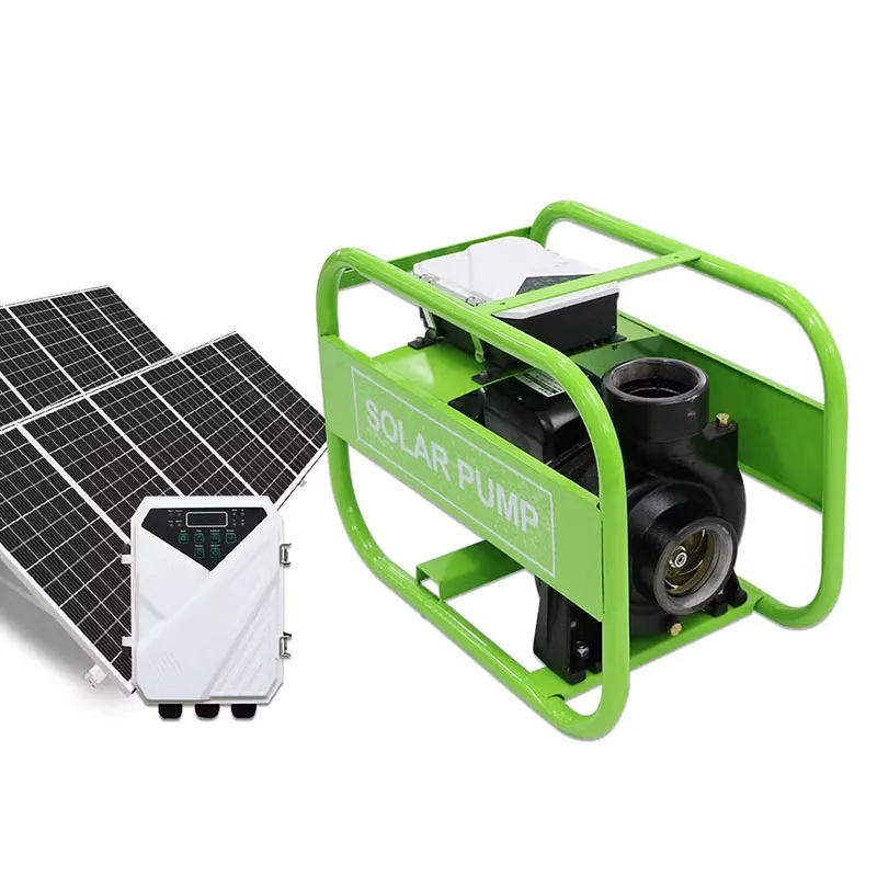
Before touching a wrench, map the full bill‑of‑materials. A clean Solar Booster Pump Installation has four subsystems:
3.1 Power Subsystem
- PV Array – monocrystalline preferred (higher yield per m²)
- Charge Controller / Pump Inverter – MPPT type, matches pump V/A curve
- Battery Bank (optional) – LiFePO₄ increasingly replaces lead‑acid for cycle life
- Fuse & Circuit Breaker – DC‑rated breakers (AC breakers arc at DC voltage!)
3.2 Pump Solar Booster Pump Installation Subsystem
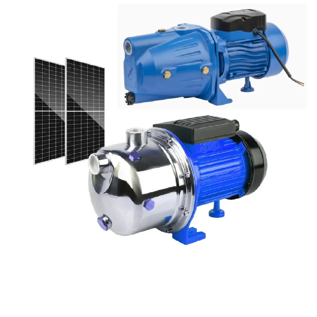
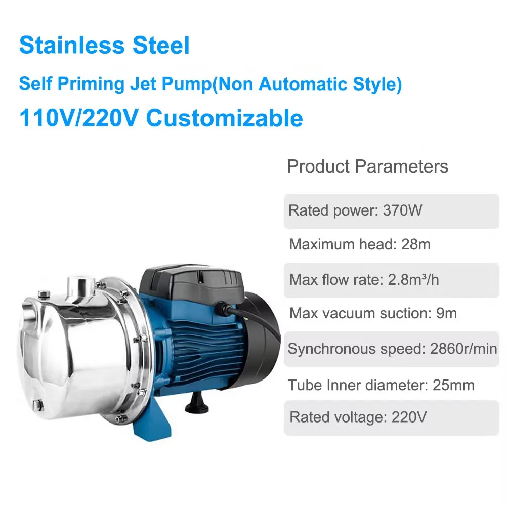
- Surface solar booster pump – centrifugal or multistage, self‑priming if suction lift exists
- Submersible solar booster pump – helical screw (shallow/debris) or multistage centrifugal (deep/clear water)
Both are core Jingong product lines; see surface models and submersible models for spec sheets.
3.3 Pressure Subsystem
- Pressure tank – absorbs pulsation, reduces pump start/stop cycles
- Pressure switch – cut‑in / cut‑out setting (typical 1.5 bar cut‑in, 3.0 bar cut‑out for home; adjust per fixture count)
- Flow gauge / pressure gauge – teed into discharge for commissioning checks
3.4 Pipeline Subsystem
- Pipe material – PVC‑U for cold / low pressure; SS304/316 for corrosive or high‑pressure
- Check valve – always on pump discharge, arrow outward
- Foot valve + strainer – on surface pump suction end (if drawing from tank/well)
- Air release valve – at high points of pipe run
4: Step‑by‑Step Solar Booster Pump Installation (The Core)
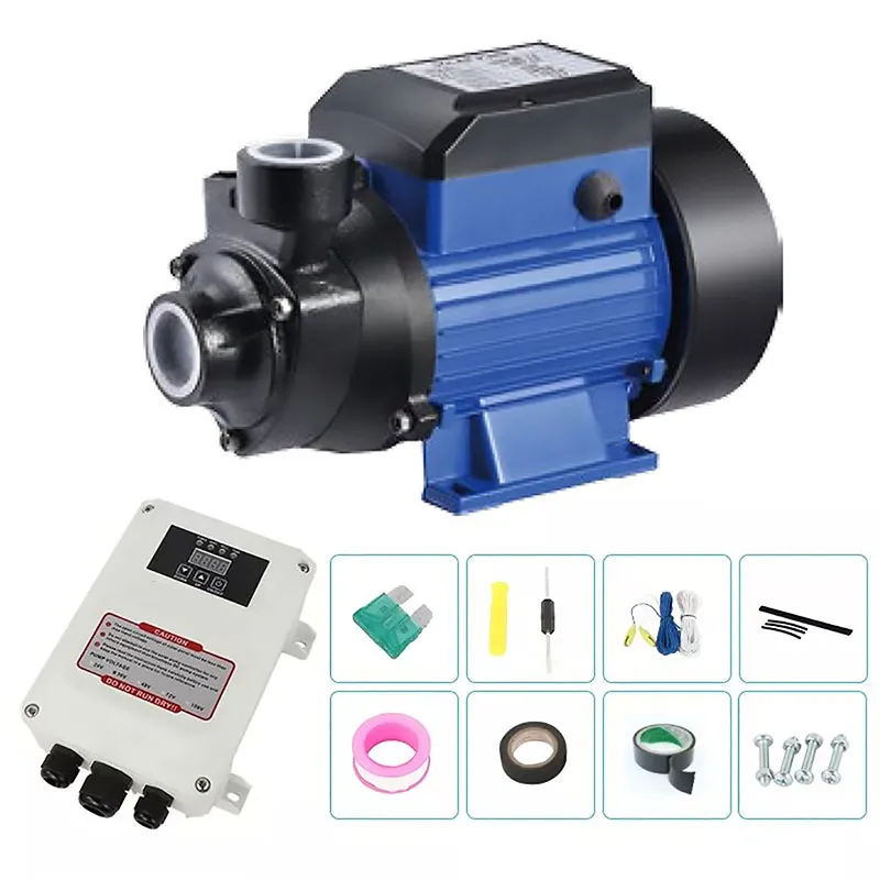
This is the highest‑traffic section of the entire post. Google sees “how to install solar booster pump” searches daily; we structure this so both surface and submersible paths are crawlable under one URL (better authority consolidation than splitting into two thin posts).
4.1 Solar Surface Booster Pump Installation (Land‑Type)
Step 1 – Mount the Pump Base
Lay a concrete plinth 30 cm above grade, minimum 40×40 cm. Bolt pump down via anti‑vibration pads. Why: surface pumps vibrate; hard‑mounting transfers vibration to pipe → joint fatigue within 12 months.
Step 2 – Suction Side (If Applicable)
- Prime the pump first if non‑self‑priming (fill volute with water before start)
- Install foot valve + strainer at suction inlet, 0.5 m above tank bottom (avoids sucking sediment)
- Suction pipe diameter ≥ pump inlet size; never reduce on suction side (causes cavitation)
- Keep suction run short (<10 m) and minimize elbows (each 90° elbow ≈ 1 m head loss)
Step 3 – Discharge Side & Check Valve
- Follow the arrow on pump body → discharge direction
- Install spring‑loaded check valve 15–30 cm downstream of pump outlet (prevents backflow when pump stops)
- Tee in pressure tank + pressure switch 30–50 cm after check valve (smooths pulsation before switch)
Step 4 – Pressure Tank Pre‑Charge Check
Before connecting water, check tank Schrader valve with tire gauge. Factory pre‑charge is usually 1.5–2.5 bar. Rule: pre‑charge = cut‑in pressure − 0.2 bar. If your pressure switch cuts in at 1.5 bar, tank should read ~1.3 bar empty.
Step 5 – Bypass Loop (Pro Tip)
Install a manual ball valve bypass around pump → lets you isolate pump for service without draining whole house line. Small detail, big maintenance win.
4.2 Solar Submersible Booster Pump Installation (Dive‑Type)
Step 1 – Rope, Not Cable
This is the mistake we see on every 3rd field visit. Never suspend a submersible by its power cable. Cable is for electrons, not tonnes of water‑logged pump. Use 8 mm polypropylene rope, tied to pump eyelet, then to well cap.
Step 2 – Lowering Depth
- Submerge minimum 1–3 m below static water level to stay under during drawdown
- Keep pump ≥1 m above well bottom (avoids sucking settled silt)
- For solar submersibles in rivers/tanks: hang 0.5 m below surface, intake screened
Step 3 – Anti‑Sway & Cable Tie
Every 3 m of descent, zip‑tie cable loosely to rope. Not tight—cable needs to hang, not carry load. At well cap, clamp cable with a cable gland (watertight PG21 or similar) so rain doesn’t track down into splice.
Step 4 – Discharge Riser & Check Valve
- Use HDPE or galvanised riser pipe, thread + seal tape
- Check valve at wellhead (or 1 m below water line for deep wells) to hold column when pump stops
- Tee to pressure tank + switch above ground
4.3 Solar Panel & Electrical Wiring (Same for Both Pump Types)
Panel Mounting
- South‑face (NH) / North‑face (SH), tilt = latitude ±5°
- Leave 10 cm gap behind panels for airflow (reduces heat loss—PV efficiency drops ~0.4 %/°C above 25 °C)
- No part of array shaded at 11 AM–1 PM solar time
Wiring Chain
- PV+ → MC4 → Charge Controller PV in+
- PV− → MC4 → Charge Controller PV in−
- Controller Bat+ → Fuse → Battery+ (or pump DC in+)
- Controller Bat− → Battery− (or pump DC in−)
- If pump is AC type: Controller/Battery → Inverter → Pump disconnect → Pump
Wire Gauge by Distance (Critical Table)
| Run Distance | Pump Power | Recommended (Copper) | Note |
|---|---|---|---|
| <10 m | ≤400 W (12/24 V) | 12 AWG | Standard PV cable OK |
| 10–20 m | 400–800 W (24/48 V) | 10 AWG | Voltage drop check required |
| 20–40 m | 800 W–1.5 kW (48 V) | 8 AWG | Consider upping to 48 V system |
| >40 m | Any | 6 AWG or go higher voltage | Undersize = hot wires + controller throttling |
AWG reference: standard AWG cross‑reference. Keep voltage drop <3 % on DC side, <2 % on AC side.
Fuse & Polarity
- Fuse on PV+ between array and controller (not on battery side unless battery‑only circuit)
- Fuse rating = 1.25 × array Isc (short circuit current)
- Double‑check polarity before closing breaker—reverse on some controllers = fried MOSFETs instantly
Waterproofing
All outdoor splices: strip → tin → heat‑shrink + adhesive lining (not plain shrink). MC4 joints already IP67, but panel‑to‑controller roof run should be clipped, not dangling.
4.4 System Integration & Bypass (Engineer‑Grade Touch)
- Reserve a manual bypass loop with ball valve so you can feed from municipal/generator if solar flatlines
- Install a sample port + pressure gauge tee on discharge for future commissioning checks
- Label every valve: “PUMP OUT”, “BYPASS”, “TANK IN”—future you (or your client) will thank you
5: System Commissioning & Post‑Installation Testing (The Pro Difference)
Anyone can bolt parts together; commissioning separates a reliable Solar Booster Pump Installation from a ticking time bomb. These tests simulate real‑world stress before handover.
5.1 Pipeline Flushing & Leakage Inspection
Before energizing the pump, open the farthest faucet and flush the system for 10 minutes. This ejects debris (solder flecks, Teflon tape, sand) that could clog nozzles or score seals. Then, close all outlets and let the system pressurize for 1 hour. A pressure drop >0.2 bar indicates a leak—check threaded joints first, as they are the usual suspects.
5.2 Dry‑Run Protection Function Test
Simulate a drought. With the pump running, manually close the inlet valve (surface pump) or partially crimp the suction hose. The controller should detect the low current/flow within 10–30 seconds and shut down, displaying a “Dry Run” or “Low Water” fault code. If the pump continues to spin, your dry‑run protection is disabled or faulty—fix this immediately.
5.3 Pressure Switch Cycling & Tank Pre‑Charge Adjustment
Observe the pressure gauge needle. It should rise steadily until it hits the cut‑out setpoint (e.g., 3.0 bar), at which point the pump stops. Open a tap slightly; pressure should drop slowly until the cut‑in point (e.g., 1.5 bar), triggering the pump to restart. Rapid cycling (more than 3 starts per minute) usually means the pressure tank’s air cushion is waterlogged. Drain the tank and re‑check the pre‑charge pressure (should be 0.2 bar below cut‑in).
5.4 Midday Load Amp Draw Test
At peak sun (11 AM–1 PM), use a clamp meter to measure the amperage on the pump input wire. Compare this reading to the rated Full Load Amps (FLA) on the motor nameplate.
- Normal: Amps are within ±10% of FLA.
- Low Amps: Suggests low voltage (thin wires/shade) or an open discharge valve.
- High Amps: Indicates mechanical binding (bad bearing) or a clogged impeller.
This test is vital for validating your wire gauge choices made earlier in the Solar Booster Pump Installation process.
5.5 Flow Rate & Head Verification
Place a 5‑gallon bucket under a discharge spigot. Time how long it takes to fill. Convert this to Liters Per Minute (LPM) or Gallons Per Minute (GPM). Compare this against the pump curve provided in our technical datasheets. A significant deviation (e.g., 20% lower flow) confirms there is a restriction or mismatch in the system design.
6: Common Installation Mistakes & Troubleshooting (Traffic Magnet)
This section targets “solar booster pump not working” searches. By addressing these common pitfalls, we reduce bounce rate and build trust.
| Symptom | Likely Cause (Installation Error) | Quick Fix |
|---|---|---|
| Pump hums but won’t start | 1. Low voltage (shaded panels) 2. Wrong wire gauge (voltage drop) 3. Controller settings locked |
Clean panels; Shorten wire run; Check MPPT settings |
| Pump runs but no water / low pressure | 1. Air leak in suction line (land pumps) 2. Clogged inlet filter 3. Foot valve stuck closed |
Seal suction joints with epoxy; Clean strainer; Replace foot valve |
| Frequent start/stop cycling | 1. Waterlogged pressure tank 2. Leaking check valve 3. Pressure switch differential too small |
Re‑pressurize tank; Replace check valve; Adjust switch screws |
| Pump overheats and shuts down | 1. Running dry (failed sensor) 2. Low flow causing motor cooling failure 3. Ambient temp too high |
Verify dry‑run sensor; Increase pipe size; Improve ventilation |
| Low flow in morning, normal at noon | 1. Battery not holding charge 2. Controller not waking up early enough |
Test battery health; Adjust “Early Start” feature on MPPT |
For complex hydraulic issues, consult our advanced troubleshooting portal.
7: Daily Maintenance & Service Life Extension (Building Trust)
A successful Solar Booster Pump Installation isn’t complete without a maintenance plan. Solar pumps are low maintenance, but “low” is not “zero.”
7.1 Routine Cleaning
- Panels: Clean dust, pollen, and bird droppings monthly. A 10% reduction in light transmittance equals a 10% drop in output. Use soft brushes and deionized water.
- Intake Screens: Inspect and rinse the foot valve strainer every 3 months, especially in silty water sources.
7.2 Seasonal Inspections
- Wet Season: Check for ground erosion around the pump pad and electrical conduit entries. Ensure critter guards are intact to prevent rodents from chewing wires.
- Dry Season: Monitor water levels closely. As the water table drops, ensure the submersible pump remains submerged to avoid sucking air.
- Winter (Cold Climates): If freezing occurs, drain the pressure tank and pump housing if the system will not be used. Ice expansion is the #1 killer of cast iron pump casings.
7.3 Cost Analysis: Solar vs. Diesel
Let’s talk ROI. A typical 1HP diesel pump consumes ~1 liter of diesel per hour. Over 5 years, fuel costs alone can exceed $5,000 USD. A solar pump has zero fuel cost. While the upfront cost of a Solar Booster Pump Installation is higher, the payback period is usually 12–24 months. After that, the water is essentially free. For areas with unreliable fuel supply, the logistical savings are incalculable.
8: FAQ (Targeting Google Featured Snippets)
These concise answers are structured to capture Position Zero in SERPs.
Can I install a solar booster pump by myself?
Yes, if you have basic plumbing and electrical skills, installing a surface solar booster pump is a manageable DIY project. However, deep well submersible pumps require specialized tools (torque arrestors, well caps) and safety gear. For submersible units, we recommend professional installation or at least a helper.
What size solar panel do I need for a booster pump?
A general rule of thumb: Total PV Wattage = Pump Rated Watts × 1.3. For a 750W pump, you need approximately 975W–1000W of solar panels. This buffer accounts for inverter losses, heat derating, and less‑than‑ideal sun angles.
Does a solar booster pump need a pressure tank?
Absolutely. A pressure tank is critical. It stores pressurized water, reducing the number of times the pump must cycle on and off. This prevents motor burnout, reduces power consumption spikes, and provides consistent pressure at the tap.
How to wire a solar booster pump correctly?
Always follow the sequence: Solar Panels → MC4 Connectors → MPPT Controller → Fuse → Battery (optional) → Pump. Never skip the fuse on the positive line. Use UV‑resistant, double‑insulated cables sized for the distance to prevent voltage drop.
What is the best installation position for a solar booster pump?
For surface pumps, install as close to the water source as possible to minimize suction lift (keep it under 8m). For submersible pumps, ensure it is fully submerged but at least 1m above the well bottom to avoid sand. Mount solar panels facing true south (NH) or north (SH) with no shading.
9: Product Recommendation & Matching (Conversion)
Now that you understand the technical depth of a Solar Booster Pump Installation, let us match you with the right hardware. As a factory‑direct supplier, Jingong offers customized solutions for every scenario.
9.1 Residential & Villa Solutions
Recommended: Jingong JGP‑Solar Series
Specs: 24V/48V DC, Built‑in intelligent controller, VFD technology for constant pressure.
Benefit: Silent operation, compact design fits in utility closets, perfect for replacing old grid‑tied pumps.
9.2 Agricultural Irrigation & Livestock
Recommended: Jingong JG‑Centrifugal Series + High‑Efficiency Monocrystalline Arrays.
Specs: High flow rates (up to 10,000 LPH), robust cast iron/stainless steel construction.
Benefit: Paired with our Diesel Backup Pumps for hybrid reliability during monsoons.
9.3 Deep Well & Borehole Solutions
Recommended: Jingong JG‑Sub Multistage Series
Specs: 304 Stainless Steel, heads up to 300m, helical screw options for sandy water.
Benefit: Corrosion‑resistant, high efficiency, designed for permanent underwater operation.
9.4 Customization & OEM Services
Need specific voltages (110V/220V/380V), frequencies (50Hz/60Hz), or branding? Jingong’s factory supports full OEM/ODM. Contact our engineering team today for a hydraulic calculation report tailored to your exact site conditions.
Request a Quote / Get Technical Support
Use Our Online Configurator